infrared remote control with Raspberry Pi Pico
- introduction
- Measuring the IR signals of the remote control
- Analyze the signal
- Schematic
- micro-python program on the pico
- final thoughts
Introduction
My Project-Audio
S2 stereo only powers on when the front button is pressed or the
remote is used. Because the setup (an S2 and a Raspberry Pi 3 with volumio)
is otherwise switchable via an RF socket, it’s frustrating to still have to
go over and manually turn on the S2.
So why not mimic the IR remote
control of the S2 using a Raspberry
Pi pico?
Measuring the IR signals of the remote control
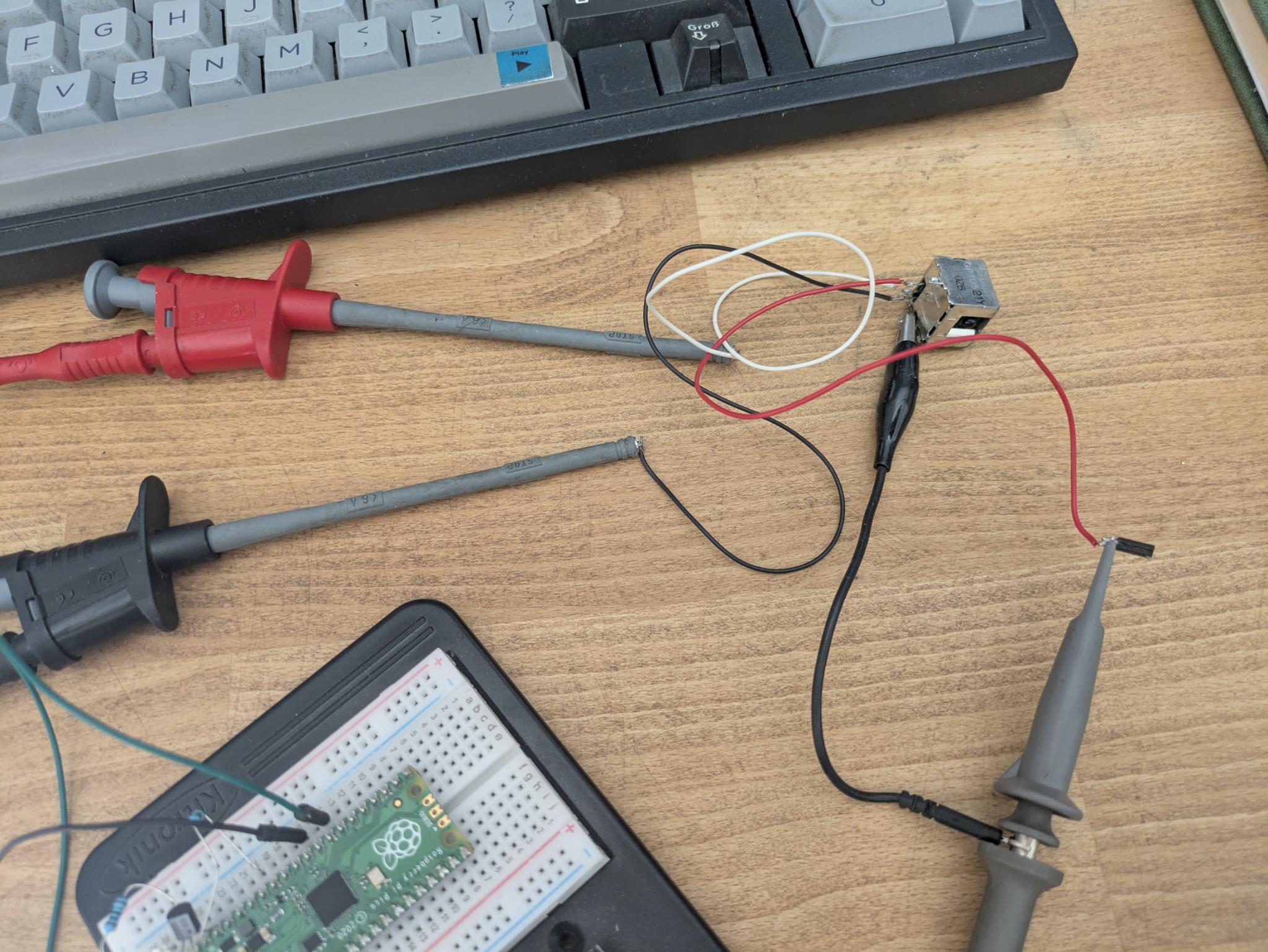
I use a Sharp GP1U521Y Light detection. It comes with with 38kHz frequency support. Its from an old video recorder I think.
Seen from front there are 3 pins on the lower back side:
Pin1 - Vout
Pin2 - Vcc
Pin3 - GND
Vmax is 6.4V
Every other TSOP with 38khz should be usable as well, the pinout should be also similar.
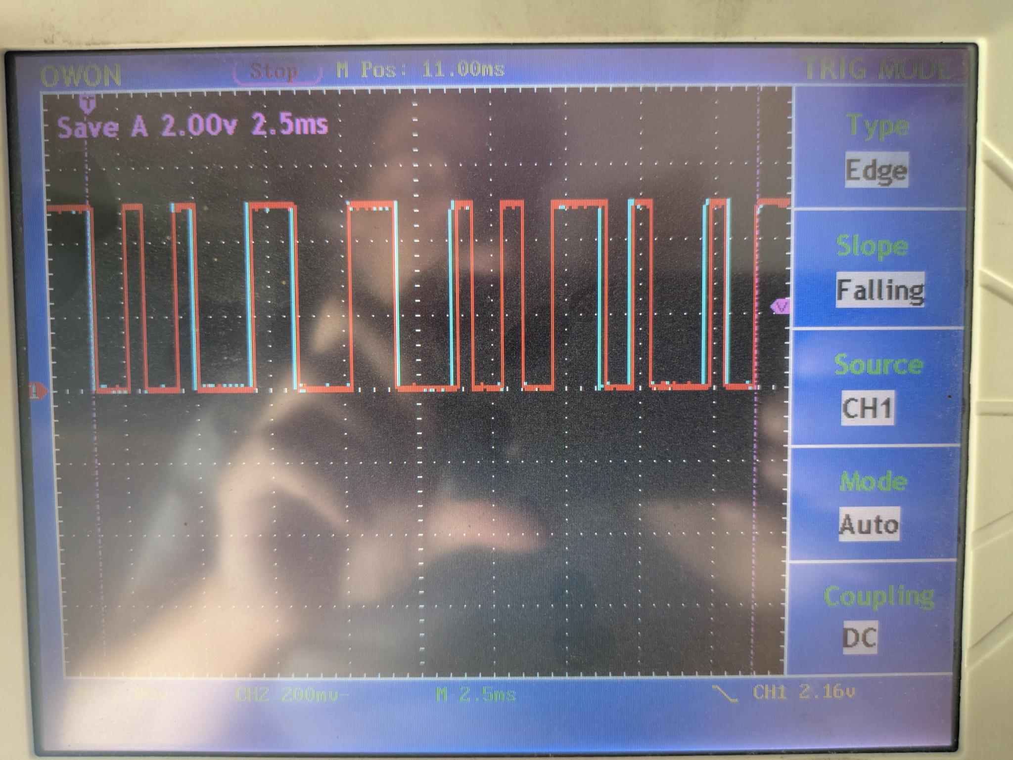
Analyze the signal
The IR pattern is analyzed by comparing recorded and measured signals,
which can be done using Save/RCL on my Owon oscilloscope. The recorded
signal can then be set to CH A on. Saving to a USB stick is not possible.
The signal is approx. 22.5 ms long.
Best settings: 2.5 ms time resolution, 2 V, Pos: 11 ms
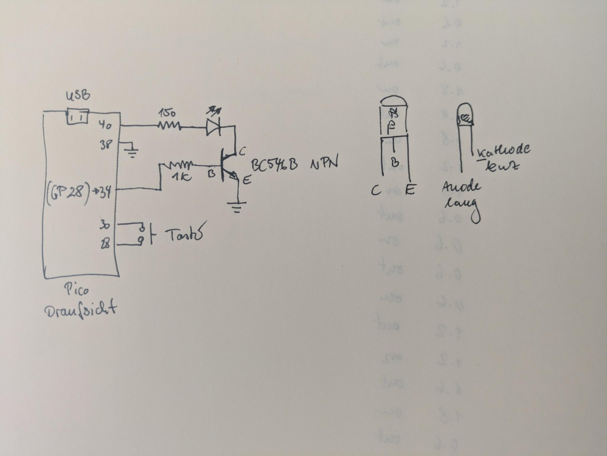
Schematic
I use this schematic to power the IR LED, which was harvested from another remote control.
micro-python program on the pico
Using thonny to transfer this micro-python program on the pico. When
naming it main.py and saving it to the pico it will directly start after
power-up.
The burst and space durations are directly measured in us with the
oscilloscope.
main.py
from machine import Pin, PWM
from time import sleep_us, sleep

# PWM-output on GP28 (with 1kOhm resistor to transistor)
pwm = PWM(Pin(28))
pwm.freq(38000)               # 38 kHz Träger [6]
pwm.duty_u16(0)               # Start: aus
led = Pin(25, Pin.OUT)        # Onboard-LED (Pico)
led.value(1)                  # turn on green LED on pico

def carrier_on(duty_pct=33):
    # duty_pct 0..100 -> 16-bit duty
    pwm.duty_u16(int(65535 * duty_pct / 100))

def carrier_off():
    pwm.duty_u16(0)

def burst(duration_us, duty_pct=33):
    carrier_on(duty_pct)
    sleep_us(duration_us)
    carrier_off()

def space(duration_us):
    sleep_us(duration_us)

sleep (5) 		#wait before sending the signal
led.value(0) 	#signal with green led that we start sending
sleep_us(90000)
led.value(1)

for _ in range(1):
    burst(800, 40)
    space(800)

    burst(800, 40)
    space(800)

    burst(1600, 40)
    space(1600)

    burst(1600, 40)
    space(1600)

    burst(1800, 40)
    space(600)

    burst(800, 40)
    space(800)

    burst(800, 40)
    space(1800)

    burst(800, 40)
    space(600)

    burst(1800, 40)
    space(600)

    burst(800, 40)
    space(100000)
carrier_off()
led.value(0)             # turn off green LED
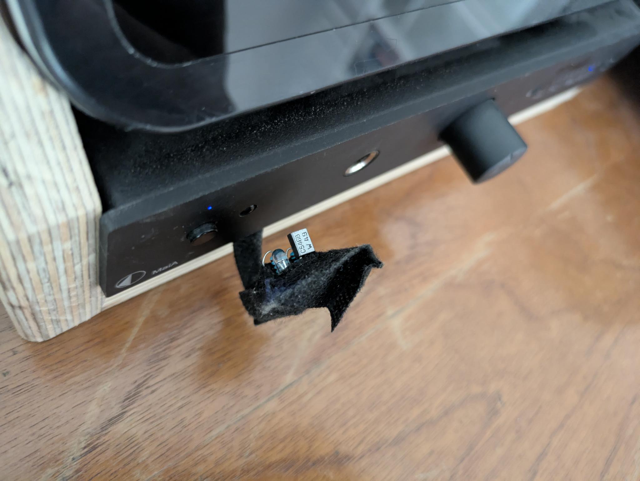
Now only the only thing that's left is to position the sender directly in from of the S2 IR receiver. The pico is powered by an USB port of the raspberry pi 3.
final thoughts
Of course I could also directly use a GPIO port of the raspberry pi 3, but the pico solution is a bit more flexible and less hassle to install.